Stock Truck Available Immediately
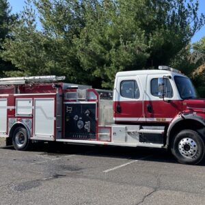
Available now and located at Fire Line Equipment: 2012 International 4×4 Commercial Pumper
CALL (717) 354-8106 FOR ADDITIONAL INFO
The E-ONE supplied components of the apparatus shall be compliant with NFPA 1901, 2009 edition.
CHASSIS MODEL
Frame Liner
A frame liner shall be provided by the chassis supplier per the chassis suppliers specifications and frame design.
CHASSIS PREP
Fire Apparatus/Rescue Prep
The following items shall be installed on the commercial chassis in preparation for fire apparatus/rescue application:
• Exhaust Extension – The chassis exhaust pipe shall be extended to the front of the right rear wheels.
• Fast Idle System – A fast idle system shall be provided and controlled by a cab or pump panel mounted switch. The system shall increase engine idle speed to a preset RPM for increased alternator output.
• Master Light Switch – The master light switch shall consist of one (1) illuminated rocker switch wired through a solenoid to accessory switches to allow pre-selected switches to be turned on or off at one time.
• Battery Master Disconnect – A heavy duty on/off single battery master disconnect switch shall be mounted in the cab within easy reach of the driver.
• Auxiliary Engine Cooler – As required for pumping applications, an engine cooler shall be installed. The engine cooler shall be required to lower engine water temperature during prolonged pumping operations and shall be controlled at the pump operator`s position.
BUMPERS
Front Bumper
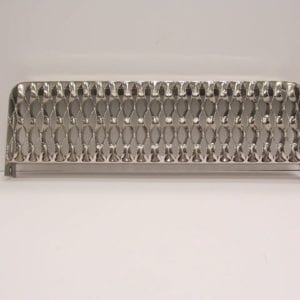
The vehicle shall be equipped with a one-piece 10” high bumper, made from 10 gauge (0.135” nominal) polished stainless steel for corrosion resistance, strength, and long-lasting appearance. It shall be mounted directly to the front frame extensions for maximum strength. The bumper shall incorporate two (2) stiffening ribs.
Front Bumper Extension
The bumper shall be extended approximately 20” from the face of the cab as required.
Bumper Gravel Shield
The extended front bumper gravel shield shall be made of 1/8” (.125”) aluminum treadplate material.
BUMPER TRAYS
Bumper Hose Tray Strap
A heavy duty 2” wide black nylon strap shall be provided for the center bumper hose tray. The strap shall be attached to the bumper gravel shield by the use of footman loops. Heavy duty Velcro shall be sewn on the strap to securely retain the hose in the tray.
Bumper Tray – Center
A hose tray constructed of 1/8” aluminum shall be recessed into the front bumper extension. The tray shall be located in the center of the bumper and be approximately 16″ deep (15″ to the top of the tiles). One inch thick black turtle tiles shall be included in the bottom of the hose tray to aid in the dissipation of water from the tray.
AXLE OPTIONS
TIRE OPTIONS
Tire Pressure Monitor
The apparatus shall be provided with tire pressure indicating valve stem caps. The indicators shall be installed on each tire and be a heavy duty design manufactured specifically for trucks. When tire is properly inflated, the indicator inside the cap shall be green, and when the tire is underinflated by 10%, the indicator inside the cap shall be red.
AIR SYSTEM OPTIONS
Air Inlet
A 1/4” male plug air hose inlet shall be connected to the air reservoir tank. A 1/4” inline check valve will be installed in the line. Air hose connection will provide the capability of filling the air brake system with air from an outside source. Location: driver’s door step area.
Air Horns
Dual air horns shall be provided, connected to the chassis air system. The horns shall be mounted through the front bumper. The front bumper shall have two (2) holes punched to accommodate the air horns. A pressure protection valve shall be installed to prevent the air brake system from being depleted of air pressure.
ENGINES & TRANSMISSIONS
Navistar Engine
The chassis shall be equipped with a Navistar Maxx Force 9 turbocharged, six-cylinder, 2010 EPA compliant, electronic engine, 330HP @ 2000 RPM, 950lb-ft torque @ 1200 RPM, 2200 RPM governed speed.
Engine accessories shall include:
MT-38 12 volt starting motor
Air cleaner restriction gauge
Cruise control with controls integral to the steering wheel
Spin-on type engine oil filter
Engine-mounted fuel filter
Vehicle Speed
The apparatus shall have a speed range of between 62 MPH and 67 MPH.
CHASSIS OPTIONS
Rear Tow Eyes
Two (2) heavy duty tow eyes made of 3/4” (0.75”) thick steel having 2-1/2” diameter holes shall be mounted below the body at the rear of the vehicle to allow towing (not lifting) of the apparatus without damage. The tow eyes will be welded to the lower end of a 5” steel channel that is bolted at the end of the chassis frame rails. The tow eyes shall be painted chassis black.
Front Tow Hooks
Two (2) heavy duty painted front tow hooks shall be securely bolted to the front chassis frame rail extensions to allow towing (not lifting) of the apparatus without damage. They shall be mounted in the downward position.
Chassis Deluxe Trim Package
A diamond plate deluxe trim package shall be provided for a Navistar four (4) door cab.
All stepping surfaces on the trim package shall be in accordance with NFPA by including a multi-directional aggressive gripping surface incorporated into the aluminum diamond plate. This surface shall extend vertically from the diamond plate a minimum of a 1/8″ (0.125″) and shall be 1″ in diameter in design with a minimum of 4″ on center. (NO EXCEPTIONS)
The driver side trim shall be full length and shall include two (2) forward upper area of door opening mounted steps and a full length lower step. Included on the driver side shall be an access area below the forward cab door to the chassis batteries, a single storage compartment with NFPA lighting below the rear cab door and a mounting surface for the battery charger receptacle and air inlet (as applicable).
The driver side trim shall include two (2) hinged doors. Each door shall have a push-button latch and shall be wired through the cab door ajar indicator.
The officer side trim shall be two (2) piece in design. The forward trim shall include an upper and lower full length step with the upper step offset rearward for access to the fuel fill. The fuel tank shall include a diamond plate wrap along the outboard side of the tank.
The rearward trim shall include one (1) forward upper area of door opening mounted step and a full length lower step. A single storage compartment shall be provided below the officer side rear cab door.
The compartment shall include a hinged door with push-button latch and shall include lighting and wired through the cab door ajar indicator per NFPA.
CAB MODEL
Cab Model
CAB 4DR INTL 7400 4×4
CAB BADGE PACKAGE
Logo Package
The apparatus shall have manufacturer logos provided on the cab and body as applicable.
MISC EXTERIOR CAB OPTIONS
Label “Diesel Fuel Only“
Located above each fuel filler housing shall be a metallic label that designates ”Diesel Fuel Only” requirements. It shall be black with white or equivalent contrasting letters a minimum of 1/2” high.
Off Road Steps[Qty: 2]
Additional non-slip type steps below the chassis cab steps shall be provided to meet NFPA 1901 first step height requirements.
SEATS
Seating Capacity Tag
A tag that is in view of the driver stating seating capacity of five (5) personnel shall be provided.
Mechanical Air Pack Bottle Bracket[Qty: 4]
Ziamatic model #QM-ROLO-SA mechanical SCBA bottle bracket(s) shall be provided to fit all SCBA bottles currently on the market. The bracket(s) shall be positive locking and be equipped with an adjustable footplate and a pull release strap.
The SCBA bracket(s) shall be equipped with a PVC coated flip down restraint to securely lock the SCBA in place without damaging the cylinder wall.
The bracket(s) shall be located in each SCBA seat.
MISC INTERIOR CAB OPTIONS
Air Horn Lanyard(s)
There shall be a ”Y” style lanyard mounted in the center of the cab to a single switch that allows the driver and officer to operate the air horns on units thus equipped. The lanyard shall activate a single center mounted electrical air switch. International chassis or similar equipped shall utilize a “Y” Lanyard attached to single chassis supplied center switch.
On commercial chassis if equipped with dual air switches one on each side overhead as delivered there shall be 2 single lanyard pulls installed one to each switch for operation from driver or officer seating position. Freightliner chassis or similar equipped shall utilize 2 individual lanyards one at each front seating position attached to supplied individual switches mounted in each side overhead.
Cab Console
The console shall be centrally located and shall allow the driver and/or officer access to all components while seated with seat belts secured.
The console shall be constructed of aluminum smooth plate with a sanded finish. The top surface shall have a non-reflective material for increased visibility of labels and controls.
All switches located on the console shall be clearly labeled and shall be back-lit for easy operation and visibility.
CAB ELECTRICAL OPTIONS
Cab Dome Lights
A Weldon LED dome light assembly with one (1) white lens and one (1) red lens and plastic housing shall be installed. The white light activates with appropriate cab door and light assembly switch, the red light activates with light assembly mounted switch only.
There shall be two (2) mounted in the front of the cab, one (1) in the driver and one (1) in the officer ceiling.
There shall be two (2) mounted in the rear of the cab, one (1) in the driver side and one (1) in the officer side ceiling.
Auto-Eject Battery Charger Receptacle
The battery charger receptacle shall be a Kussmaul 20 amp NEMA 5-20 Super Auto-Eject #091-55-20-120 with a cover. The Super Auto-Eject receptacle shall be completely sealed and have an automatic power line disconnect.
The receptacle shall be located driver’s door step area and the cover color shall be Yellow.
Horn Button Switch
A three (3) position rocker switch shall be installed in the cab accessible to driver and properly labeled to enable the operator to activate the OEM traffic horn, electronic siren or Federal Signal Q2B siren from the steering wheel horn button.
Air Compressor and Battery Conditioner
A Supersmart microprocessor controlled battery charging system shall be installed and Kussmaul Auto Pump 120.
The battery charging system shall have a 110 volt 60 hertz input with a 20 amp DC output.
The system shall provide a signal by a remote charge indicator panel if battery voltage drops below 11.5 volts. The remote panel shall be located next to the inlet receptacle.
The microprocessor is continuously powered from the battery to provide charge status. Equalization charge only occurs when necessary, not with every cycle.
The system will fully charge batteries while allowing up to 8 amps of parasitic load.
The air compressor shall be a Kussmaul 091-9B-1 powered by 120 volt 60 hertz input from the inlet receptacle with an output of .76 cfm at 100 psi. Includes a miniature air filter with transparent bowl and pressure switch that senses the system pressure and operates the compressor whenever the pressure in the air brake system drops below a pre-determined level.
Headlights for 4×4 Commercial Chassis
A pair of dual headlights (Hi/Low beam) with bezel shall be provided. The lights shall be locate in extended front bumper as far outboard as possible and recess mounted to protect the lights. The lights positioning and height shall be within FMVMS requirements.
The lights shall be in place of commercial chassis bumper mounted lighting.
BODY COMPT LEFT SIDE
Driver Side Assembly
The driver side assembly shall be constructed entirely of aluminum extrusions and interlocking aluminum plates. This aluminum modular design shall provide a high strength-to-weight ratio for increased equipment carrying capacity.
The driver side body corners shall be 6063-T5 extruded aluminum corner sections with a 3/16” (0.188”) wall thickness. The side body extrusions shall be 6063-T5 aluminum tubing with a 3/16” (0.188”) wall thickness and 3/16” (0.188”) outside corner radius. The corners and sides shall be welded both internally and externally at each joint using an aluminum alloy welding wire.
The driver side body shall be completely sanded and deburred to assure a smooth finish and painted job color.
Driver Side Compartments
The three (3) driver side compartments shall be constructed from 3003 H14 1/8” (.125”) smooth aluminum plate. The compartments shall be modular in design and shall not be a part of the body support structure.
There shall be one (1) compartment located ahead of the rear wheels. This compartment shall be approximately 36” wide x 68.75” high x 23.75” deep and contain approximately 34.02 cu. ft. of combined storage space. The door opening shall be approximately 36” wide x 68” high.
There shall be one (1) compartment located over the rear wheel. The compartment shall be approximately 56” wide x 34.75” high x 23.75” deep and contain approximately 26.75 cu. ft. of storage space. The door opening shall be approximately 56” wide x 34” high.
There shall be one (1) compartment located behind of the rear wheels. This compartment shall be approximately 45” wide x 68.75” high x 23.75” deep and contain approximately 42.52 cu. ft. of combined storage space. The door opening shall be approximately 45” wide x 68” high.
Each compartment seam shall be sealed using a permanent pliable silicone caulk. The walls of each compartment shall be machine-louvered for adequate ventilation.
An externally-mounted compartment top shall be provided and constructed of a 1/8” (.125”) aluminum treadplate. The compartment top shall be removable for easy access to the main body wiring harness.
Driver Side Roof Top Compartments
Two (2) driver side roof compartments shall be provided. The compartments shall be constructed of 3/16″ (.187″) aluminum treadplate.
The compartments shall be transverse front to rear.
The compartment top access doors shall be raised and constructed of 1/8” (.125”) aluminum treadplate. The access doors shall include stainless steel hinges and shall be hinged to the outside of the compartment. Each lid shall include turn latches, grab handle(s) and be wired to the door ajar indicator in the cab.
The compartment shall have vertically hinged access door at the rear constructed of 1/8” (.125”) aluminum treadplate. The access door shall include push button latch and be wired to the door ajar indicator in the cab.
Lighting shall be provided for the compartment. The light(s) shall illuminate when the access door is in the open position.
BODY COMPT RIGHT SIDE
Officer Side Assembly
The officer side assembly shall be constructed entirely of aluminum extrusions and interlocking aluminum plates. This aluminum modular design shall provide a high strength-to-weight ratio for increased equipment carrying capacity.
The officer side body corners shall be 6063-T5 extruded aluminum corner sections with a 3/16” (0.188”) wall thickness. The side body extrusions shall be 6063-T5 aluminum tubing with a 3/16” (0.188”) wall thickness and 3/16” (0.188”) outside corner radius. The corners and sides shall be welded both internally and externally at each joint using an aluminum alloy welding wire.
The officer side body shall be completely sanded and deburred to assure a smooth finish and painted job color.
Officer Side Compartments
The three (3) officer side compartments shall be constructed from 3003 H14 1/8” (.125”) smooth aluminum plate. The compartments shall be modular in design and shall not be a part of the body support structure.
There shall be one (1) compartment located ahead of the rear wheels. This compartment shall be approximately 36” wide x 68.75” high x 23.75” deep and contain approximately 34.02 cu. ft. of combined storage space. The door opening shall be approximately 36” wide x 68” high.
There shall be one (1) compartment located over the rear wheel. The compartment shall be approximately 56” wide x 34.75” high x 23.75” deep and contain approximately 26.75 cu. ft. of storage space. The door opening shall be approximately 56” wide x 34” high.
There shall be one (1) compartment located behind of the rear wheels. This compartment shall be approximately 45” wide x 68.75” high x 23.75” deep and contain approximately 42.52 cu. ft. of combined storage space. The door opening shall be approximately 45” wide x 68” high.
Each compartment seam shall be sealed using a permanent pliable silicone caulk. The walls of each compartment shall be machine-louvered for adequate ventilation.
An externally-mounted compartment top shall be provided and constructed of a 1/8” (.125”) aluminum treadplate. The compartment top shall be removable for easy access to the main body wiring harness.
Officer Side Roof Top Compartments
Two (2) officer side roof compartments shall be provided. The compartments shall be constructed of 3/16″ (.187″) aluminum treadplate.
The compartments shall be transverse front to rear.
The compartment top access doors shall be raised and constructed of 1/8” (.125”) aluminum treadplate. The access doors shall include stainless steel hinges and shall be hinged to the outside of the compartment. Each lid shall include turn latches, grab handle(s) and be wired to the door ajar indicator in the cab.
The compartment shall have vertically hinged access door at the rear constructed of 1/8” (.125”) aluminum treadplate. The access door shall include push button latch and be wired to the door ajar indicator in the cab.
Lighting shall be provided for the compartment. The light(s) shall illuminate when the access door is in the open position.
BODY COMPT REAR
Upper Storage Compartment
Upper Storage Compartment to hold (1) 17` Little Giant ladder, (1) 24` 2-section ladder, (1) 14` roof ladder, (1) 10` attic ladder and (2) pike poles.
Rear End Assembly
The rear body shall be constructed entirely of aluminum extrusions and interlocking aluminum plates and includes a full height center rear compartment.
The rear body frame shall be 6063-T5 1.5” x 4” and 1.5” x 3”aluminum extrusions with a 3/16” (0.187”) wall thickness and 3/16” (0.188”) outside corner radius and 3/16” (0.187”) aluminum smooth plate. The rear extrusions shall be welded both internally and externally at each joint using an aluminum alloy welding wire.
Storage Compartment
A storage compartment shall be provided above the rear compartment. The compartment shall be approximately 46” wide x 19” high x length of hosebed.
The compartment floor shall be constructed entirely from maintenance-free, 3/4” deep x 7.5” wide, extruded aluminum slats that shall be pop-riveted into a one-piece grid system. Each slat shall have all sharp edges removed and have an anodized ribbed top surface that shall prevent the accumulation of water and allow for ventilation of wet contents.
There shall be one (1) divider provided the full fore-aft length of the compartment. This divider shall provide additional support for the upper hosebed and shall provide separation of contents stored in the area.
The divider shall be constructed of 1/4” (0.25”) smooth aluminum plate with an extruded aluminum base welded to the top and the bottom. The divider shall be natural finish aluminum for long-lasting appearance and shall be sanded and deburred to prevent damage to the contents.
The compartment shall be used for miscellaneous storage.
The compartment shall include a vertically hinge double door with D-ring latch to secure contents. The compartment door shall be securely attached with a stainless steel piano type hinges with 1/4” pins. The hinges shall be ”staked” on every other knuckle to prevent the pin from sliding. The door shall be wired to the door ajar indicator light in the cab and shall be interlocked with the parking brake per NFPA.
Tailboard
Tailboard Step
A tailboard step shall be provided at the rear of the body. The tailboard shall 16” in depth and in accordance with NFPA in both step height and stepping surface. The maximum rear step height to the tailboard shall not exceed 24”.
The tailboard step shall be formed from 3/16” (0.188”) aluminum treadplate and shall be reinforced with 6063-T5 1.5” x 3” aluminum extrusion. The tailboard shall be in accordance with current NFPA requirements and shall include a multi-directional aggressive gripping surface incorporated into the diamond plate. The surface shall extend vertically from the diamond plate sheet a minimum of 1/8” (0.125”). Gripping surfaces shall be circular in design, a minimum of 1” diameter and on centers not to exceed 4”.
The tailboard step shall be bolted on to the body from the underside assuring a clear surface and shall be easily removable for replacement in the case of damage.
Rear Access Handrails
Handrails shall be provided at the rear of the body to assist ground personnel accessing the tailboard step and hosebed area. Each handrail shall be constructed of 6063T5 1.25” OD anodized aluminum tube, with an integral ribbed surface to assure a good grip for personnel safety, and shall be mounted between chrome stanchions.
The handrails shall be located- two (2) handrails, one (1) on each side, appropriately sized handrail mounted vertically on the trailing edge of the body and appropriately sized handrail(s) mounted horizontally below the rear hosebed opening.
DOORS
Roll Up Compartment Door
A ROM brand roll up door with satin finish shall be provided on a compartment up to 45” tall. The door(s) shall be installed in the following location(s): L2, R2.
The Robinson door slats shall be double wall box frame and manufactured from anodized aluminum. The slats shall have interlocking end shoes on each slat. The slats shall have interlocking joints with a PVC/vinyl inner seal to prevent any metal to metal contact and inhibit moisture and dust penetration.
The track shall be anodized aluminum with a finishing flange incorporated to provide a finished look around the perimeter of the door without additional trim or caulking. The track shall have a replaceable side seal to prevent water and dust from entering the compartment.
The doors shall be counterbalanced for ease in operation. A full width latch bar shall be operable with one hand, even with heavy gloves. Securing method shall be a positive latch device.
A magnetic type switch integral to the door shall be supplied for door ajar indication and compartment light activation.
The door opening shall be reduced by 2” in width and approximately 8-9” in height depending on door height.
Roll Up Compartment Door
A ROM brand roll up door with satin finish shall be provided on a compartment greater than 45” tall. The door(s) shall be installed in the following location(s): L1, L3, R1, R3.
The Robinson door slats shall be double wall box frame and manufactured from anodized aluminum. The slats shall have interlocking end shoes on each slat. The slats shall have interlocking joints with a PVC/vinyl inner seal to prevent any metal to metal contact and inhibit moisture and dust penetration.
The track shall be anodized aluminum with a finishing flange incorporated to provide a finished look around the perimeter of the door without additional trim or caulking. The track shall have a replaceable side seal to prevent water and dust from entering the compartment.
The doors shall be counterbalanced for ease in operation. A full width latch bar shall be operable with one hand, even with heavy gloves. Securing method shall be a positive latch device.
A magnetic type switch integral to the door shall be supplied for door ajar indication and compartment light activation.
The door opening shall be reduced by 2” in width and approximately 8-9” in height depending on door height.
SHELVES
Adjustable Shelf
There shall be an aluminum adjustable shelf provided for compartment L1, R1, R2, R3.
The shelf shall be constructed of 3/16” (.187”) smooth aluminum plate. The shelf shall have a minimum 2” front and rear lips to accommodate optional plastic interlocking compartment tile systems. For additional strength and reinforcement of the shelf a return break shall be provided on the outward lip. The adjustable shelf shall be capable of holding 250 lbs.
The shelf shall be sized, width and depth, to match the size and location in the compartment.
Adjustable Tracks
Tracks shall be provided in L1, R1, R2, R3 for use with adjustable shelves and/or trays in deep non-transverse compartments. The tracks shall be vertically mounted and attached to the side and/or rear walls of the compartments.
TRAYS / TOOLBOARDS
Roll-Out/Tilt Down Tray
A roll-out/tilt-down tray(s) shall be floor mounted in compartment(s) L2, R2. For use on single depth or rescue style compartment trays.
The tray(s) shall be constructed of 3/16” (.187”) smooth aluminum plate with welded corners for increased strength and rigidity. The tray shall be sized in width and depth as applicable.
An Innovative Industries SlideMaster Tip Down frame and channel assembly shall be provided for the tray(s) for the ease of operation and long service life. A positive twist lock shall be provided to secure the tray(s) in the stored position. The tray(s) shall roll-out approximately 90% from the stored position and shall tip 30 degrees downward from horizontal.
The capacity rating of the tray, in the extended position, shall be 250 lb. distributed.
Roll-Out Tray
There shall be a floor mounted roll-out tray provided in compartment R3.
The roll-out tray shall be constructed of 3/16” (.187”) smooth aluminum plate with a sanded finish and welded corners for increased strength and rigidity. The tray shall be sized in width and depth as applicable.
The drawer slides shall permit the tray to roll out of the compartment approximately eighty percent of the compartment depth. The tray shall utilize a pneumatic shock to secure the tray in the open or closed position.
The tray shall have a total capacity of 500 lbs.
Roll-Out/Tilt-Down Tray
A roll-out/tilt-down tray shall be adjustable mounted in compartment R3. For use on single depth or rescue style compartments.
The tray shall be constructed of 3/16” (.187) aluminum with welded corners for strength and rigidity. The tray shall be sized in width and depth as applicable.
An Innovative Industries SlideMaster Tip Down frame and channel assembly shall be provided for the tray for the ease of operation and long service life. A positive twist lock shall be provided to lock the tray in the stored position. The tray shall roll out approximately 90% from its stored position and shall tip 30 degrees from horizontal.
The capacity rating of the tray, in the extended position, shall be 250 lbs. distributed.
Toolboard[Qty: 2]
An adjustable roll-out aluminum toolboard(s) shall be provided for compartment(s) L3.
The toolboard shall be constructed of 3/16” (.187”) smooth aluminum plate with a sanded finish and be sized in height and depth as applicable.
The toolboard shall be mounted on drawer slides, at the top and bottom, that will permit the board to roll out of the compartment for easier access to tools and/or equipment. The slide mechanisms shall have ball bearings for ease of extension and retraction operation and dependable service. The toolboard shall be mounted at top and bottom on adjustable tracking for ease of placement.
The capacity rating shall be 250 lbs. maximum at full extension. A pneumatic shock shall be utilized to secure the toolboard in the open or closed position.
Roll-Out Tray
There shall be an adjustable roll-out tray provided in compartment R3.
The roll-out tray shall be constructed of 3/16” (.187) smooth aluminum with welded corners for strength and rigidity. The tray shall be sized in width and depth as applicable.
For greater tray accessibility, the drawer slides shall feature one hundred percent extension. The tray shall utilize a gas shock to hold the tray in an open or closed position.
The tray shall have a total capacity of 500 lbs.
Runningboard Suction Tray
A running board suction hose storage tray (approx. 35″W) shall be provided and located in the officer side running board.
The tray shall be recessed mounted and constructed of 1/8” (.125”) aluminum diamond plate (exterior) with a smooth sanded surface interior. The bottom of the tray shall have drain holes to allow water drainage from hose stored in the tray.
The tray shall be covered with a heavy duty Turtle Tile brand [#COL] floor matting.
COVERS
Rear Hose Bed Cover
A cover constructed of [#COL] 18 oz. PVC vinyl coated polyester shall be installed at the rear apparatus hose bed. The base fabric shall be 1000 x 1300 Denier Polyester with a fabric count of 20 x 20 per square inch.
The top of the cover shall be mechanically attached to the rear hose bed cover extrusion. The lower portion of the cover shall be secured in place with heavy duty nylon straps to comply with the latest edition of NFPA 1901.
Vinyl Crosslay Cover
A cover constructed of [#COL] 18 oz. PVC vinyl coated polyester shall be installed on the crosslay. The base fabric shall be 1000 x 1300 Denier Polyester with a fabric count of 20 x 20 per square inch.
The cover shall be held in place across the top of the body by chrome snaps. The sides of the cover shall have integral flaps that extend down to cover the sides of the crosslay. The side flaps shall be secured in place to comply with the latest edition of NFPA 1901.
Running Board Hose Tray Cover
A cover constructed of .125″ (1/8″) diamond plate shall be installed over the opening of the apparatus running board hose tray. The cover shall include push button latches and Gator Grip.
The cover shall be secured in place to comply with the latest edition of NFPA 1901.
Location: officer side running board.
Running Board Tray Securing Strap
A heavy duty black nylon strap with an aluminum quick-release buckle shall be provided for the running board hose tray(s). The strap shall be attached to the inboard side of the tray as low as practical to allow cinching of strap for securing tray contents and shall not reduce the overall tray capacity.
Location: officer side running board.
NFPA Hose Bed Cover
The hose bed area shall have a two (2) piece aluminum hose bed cover. The hose bed cover shall be provided in compliance with NFPA.
Each hose bed cover shall be constructed of an aluminum tubing frame with a 1/8” (.125”) aluminum treadplate top and a 3/32” (.094”) aluminum smooth plate bottom. (No Exceptions).
Each cover door shall be securely attached to the hose bed side with a full-length stainless steel piano type hinge. The hinge shall have 1/4” pins and shall be ”staked” on every other knuckle to prevent pin slippage.
The forward area of the cover shall include two (2) hold opens. The forward area of the cover shall have one (1) pneumatic shock. The rear of the cover shall have one (1) rearward mounted positive hold open/hold closed that shall include one (1) manually engaged securing pin. (no exceptions).
Each cover door shall be wired to the door ajar indicator light in the cab and shall be interlocked with the parking brake per NFPA.
The water tank fill tower(s) shall be accessible with the covers in the closed position through a diamond plate door. The fill tower access door shall be constructed of 3/16” (.187”) aluminum treadplate. The door shall be hinged and shall include one (1) hold down and grab handle.
The covers shall be supported in the closed position by a center mounted hose bed divider. The divider shall be constructed of 1/4”(.25”) smooth aluminum plate with a DA type finish. The divider shall run the full length of the hose bed (as applicable) and shall include an upper ”C” channel extrusion base.
The rear of the center mounted divider shall include a recessed area to allow for looping of hose from one side of the divider to the other.
The cover shall include two (2) assist handles; one (1) grab handle and one (1) hand rail (rear of cover). The rearward hand rails shall be installed in compliance with current NFPA. The hand rails shall be constructed of 6063-T5 1.25” OD anodized aluminum tube, with an integral ribbed surface to ensure a good grip, and will be mounted between stanchions.
A landing platform shall be provided and positioned at the upper center rear of the apparatus for assisting with cover operations. The platform shall be constructed of 3/16” (.187”) embossed aluminum treadplate.
PUMP MODULE
Upper Pump Module
An aluminum extruded upper pump module with a forward area for a triple crosslay and dunnage storage shall be provided. The upper pump module shall be constructed entirely of aluminum extrusions and interlocking aluminum plates. The upper pump module design and mounting shall allow the upper area of the pump module to be reconfigured to meet possible future needs or growth of the department. The exterior surface of the upper pump module shall have a sanded finish.
Crosslay Triple Preconnect Storage
The module design shall include an area for a double stacked triple crosslay. The forward two (2) crosslay areas shall have a capacity of 300 ft. of 1.75″ double jacket hose. The rearward crosslay area shall have the capacity for 300 ft. of 1.75″ double jacket hose or 250 ft. of 2.5″ double jacket hose. The crosslay floor shall be constructed of 3/16″ (.188) smooth aluminum plate and shall be slotted to prevent the accumulation of water and allow for ventilation of wet hose. Two (2) 1/4″ (.25″) smooth aluminum plate non-adjustable dividers with a sanded finish shall be provided to separate the three (3) hose storage areas.
Dunage Pan
A dunnage pan constructed of 3/16″ (.188″) aluminum treadplate shall be located rearward of the crosslays. The dunnage pan shall be sized to maximize available storage space.
Pump Module Width
Pump module shall be 76″ wide.
Lower Pump Module
An aluminum extruded lower pump module shall be provided and located forward of the body. The pump module shall be constructed entirely of aluminum extrusions and interlocking aluminum plates. The pump module design and mounting shall be separate from the body to allow the pump module and body to move independently of each other in order to reduce stress from frame twisting and vibration. The exterior surface of the pump module shall have a sanded finish. The pump module panel opening shall be 39” in width.
Pump Module Running Boards
The pump module shall include a running board on each side of the pump module. The running boards shall be in accordance with NFPA in both step height and stepping surface. The maximum step height to each running board shall not exceed 24”. The running boards shall be formed from 1/8” (.125”) aluminum treadplate. Each running board shall include a multi-directional, aggressive gripping surface incorporated into the treadplate. The surface shall extend vertically from the diamond plate sheet a minimum of 1/8” (.125”). Gripping surfaces shall be circular in design, a minimum of 1” diameter and on centers not to exceed 4”. Each running board shall be bolted on to the pump module and be easily removable for replacement in the case of damage.
PUMP PANELS
Hinged Gauge Panel
The driver side stainless steel single gauge panel shall be positioned where it can be opened downward for access to gauges and other interior pump module mounted items. The gauge panel shall include latches to secure the panel in the closed position. Two (2) cable tethers shall be provided to hold the panel in the open position.
Pump Access Door
The officer side pump panel shall be vertically hinged.
The pump panels shall be securely attached with a vertical stainless steel piano type hinge with 1/4” pins along the forward edge of the pump module. The hinge shall be ”staked” on every other knuckle to prevent the pin from sliding. The panels shall have push button style latches to secure the panels in the closed position and one (1) pneumatic shock to hold the upper panel in the open position.
Zolatone Pump Panels
The driver and officer side pump panels shall have a black zolatone painted finish.
MISC PUMP PANEL OPTIONS
Pump Panel Tags
Color coded pump panel labels shall be supplied to be in accordance with NFPA 1901 compliance.
Mechanically Fastened Tags
All tags installed on the exterior of the apparatus shall be mechanically fastened with stainless steel screws. These include but not limited to tags installed on the pump module, body, cab and bumper. Pump panel tags shall be mechanically fastened regardless whether panel is enclosed behind a door.
PUMP MODULE OPTIONS
Pump Module Crosslay Divider Notch
The crosslay divider(s) shall be notched on both ends for line(s) nozzle end storage with NFPA cover(s) in the closed position.
Module Logos
Logos with the OEM brand name shall be provided and shall be mounted one (1) each side on pump module/pre-connect panels. Logos shall be sized as applicable to available space on panel(s).
WATER TANK
400 Gallon Water Tank
A 400 gallon (U.S.) ”R” booster tank shall be supplied. The booster tank shall be of a pinned baffle design. The booster tank shall be completely removable without disturbing or dismounting the apparatus body structure.
The booster tank top, sides, and bottom shall be constructed of 1/2” (0.50”) black UV-stabilized copolymer polypropylene. The copolymer polypropylene tank material shall be welded together utilizing thermoplastic welding technology. A clean hot air temperature controlled process, shall ensure that each weld reaches its plasticized state without cold or hot spots. The copolymer polypropylene material shall be used for its high strength and corrosion resistance for a prolonged tank life.
The booster tank shall have a fill tower with a rearward hinged lid. The fill tower shall be located in the forward area of the tank and shall assist with tank ventilation. The fill tower shall include a removable 1/4” (0.25”) thick polypropylene screen.
The booster tank shall have two (2) tank plumbing openings. One (1) for a tank-to-pump suction line with an anti-swirl plate, and one (1) for a tank fill line. A 3” cleanout plug shall be shall be provided at the bottom of the tank sump.
The booster tank shall include longitudinal and latitudinal baffles. The baffles shall be interlocking and thermo welded to the shell of the tank to minimize water surge during travel and provide enhanced road handling stability. The baffle design shall allow waterflow in accordance with NFPA during tank filling or pump operations.
A 2.5` length of black flex hose shall be installed to the bottom of the tank. This shall direct the draining of overflow water past the rear axle and fuel tank, thus reducing the possibility of freeze-up of these components in cold environments. This drain configuration shall also assure that rear axle tire traction shall not be affected when moving forward.
The booster tank shall undergo extensive testing prior to installation in the truck. The testing shall include an electronic spark and tank fill test after both the internal and external tank shell welds are completed.
A lifetime manufacture`s limited warranty shall be included.
Tank capacity is 400 US gallon / 333 Imperial gallons / 1514 Liters.
TANK PLUMBING
Tank Fill 2 Akron Valve
One (1) 2” pump-to-tank fill line having a 2” manually operated full flow valve. The valve control shall be located at the pump operator`s panel and shall visually indicate the position of the valve at all times. The fill line shall be controlled using a chrome handle with an integral tag.
The valve shall be an Akron 8800HD series with a 316 stainless steel ball and dual polymer seats for ease of operation and increased abrasion resistance. The valve shall have a self-locking ball feature using an automatic friction lock design to balance the stainless steel ball when in a throttle position with water flowing through it.
The valve shall be of unique Akron swing-out design to allow the valve body to be removed for servicing without disassembling the plumbing.
All fabricated piping shall be a minimum of Schedule 10 stainless steel for superior corrosion resistance and decreased friction loss.
Tank To Pump
One (1) manually operated 3” Akron valve shall be installed between the pump suction and the booster tank. Includes flex hose with stainless steel hose clamps for connection to the 4″ tank sump outlet . The valve control shall be located at the pump operator`s panel and shall visually indicate the position of the valve at all times.
The valve shall be an Akron 8800HD series with a 316 stainless steel ball and dual polymer seats for ease of operation and increased abrasion resistance. The valve shall have a self-locking ball feature using an automatic friction lock design to balance the stainless steel ball when in a throttle position and water is flowing through it.
The valve shall be of the unique Akron swing-out design to allow the valve body to be removed for servicing without disassembling the plumbing.
All fabricated piping shall be a minimum of Schedule 10 stainless steel for superior corrosion resistance and decreased friction loss.
A check valve shall be provided in the tank to pump supply line to prevent the possibility of “back filling” the water tank. The valve control shall be located at the pump operator`s panel and shall visually indicate the position of the valve at all times.
LADDER STORAGE / RACKS
Ladder Brand
The ladder brand capable of being carried on the unit shall be Alco-Lite.
Ladders
The length of ladders capable of being stored shall be the following: 24′ 2-section and 14′ roof ladder.
HANDRAILS / STEPS
Hose Bed Folding Steps
Dual lighted LED folding steps shall be positioned to the driver side rear of the body. The steps shall be NFPA compliant for access to the hose bed storage area and in step height and surface area. The steps shall be staggered stepped as applicable with tailboard depth, not applicable with recessed step mounting.
Dual lighted LED folding step with LED lights integral to the step on the top to provide NFPA requirements of 2 FC on the stepping surface. Each step shall also have a LED light integral to the bottom of the step to meet NFPA requirements of a stepping surface up to 18” below the step.
The folding step shall sustain a minimum static load of 500 lbs. The folding step shall also meet NFPA slip resistance qualifications.
One (1) hand rail shall be installed (as applicable) in compliance with current NFPA. The hand rail shall be constructed of 6063T5 1.25” OD anodized aluminum tube, with an integral ribbed surface to assure a good grip for personnel safety, mounted between chrome stanchions.
Slide-Out Platform
A slide-out platform shall be provided integral with the driver side running board adjacent to the pump panel. The platform shall be 21” deep and shall be constructed of 1/8” (0.125”) aluminum treadplate with a multi-directional, aggressive gripping surface. The platform shall utilize a maintenance-free slide system incorporating stainless steel shoulder bolts that slide in slotted heavy-wall aluminum angles. Notches shall be provided at each end of the slots to hold the platform in both the extended and retracted positions.
The NFPA pump throttle height requirement shall be measured from the top of the slide-out platform on all aerials and from the ground on side mounted pump operator panels on non-aerial apparatus.
MISC BODY OPTIONS
Rear Mud Flaps
The rear tires shall have a set of black mud flaps mounted behind the rear chassis wheels with E-ONE logo.
Body Height and Mainframe Construction
The body mainframe shall be entirely constructed of aluminum. The complete framework shall be constructed of 6061T6 and 6063T5 aluminum alloy extrusions welded together using 5356 aluminum alloy welding wire.
The body mainframe shall include 3” x 3” 6061-T6 aluminum 3/8” (0.375”) wall crossmember extrusion or 3″ x 3″ I-beam section aluminum extrusion depending on the application at the front of the body . A solid 3” x 3” ”I-beam” section aluminum extrusion shall be provided the full width of the body forward and rearward of the rear wheel well. The crossmembers shall be designed to support the compartment framing and shall be welded to 1-3/16” x 3” (1.188” x 3”) solid 6063-T5 aluminum frame sill extrusions. The frame sill extrusions shall be shaped to contour with the chassis frame rails and shall be protected from contact with the chassis frame rails by 5/16” x 2” (0.31” x 2”) fiber-reinforced rubber strips to prevent wear and galvanic corrosion caused when dissimilar metals come in contact.
Body Mounting System
The main body shall be attached to the chassis frame rails with six (6) of 5/8” (0.625”) diameter steel U-bolts. This body mounting system shall be used to allow easy removal of the body for major repair or disassembly.
Water Tank Mounting System
The body design shall allow the booster tank to be completely removable without disturbing or dismounting the apparatus body structure. The water tank shall rest on top of a 3” x 3” frame assembly covered with rubber shock pads and corner braces formed from 3/16” angled plate to support the tank. The booster tank mounting system shall utilize a floating design to reduce stress from road travel and vibration. To maintain low vehicle center of gravity the water tank bottom shall be mounted within 5” of the frame rail top.
Hosebed Side Assembly
The hosebed side assemblies shall be made of 3” x 3” slotted aluminum extrusion and 3/16” (.188”) smooth plate. The hosebed side assemblies shall provide a 90” high body.
The exterior hosebed side surface shall be completely sanded and deburred to assure a smooth finish and painted job color. The interior hosebed side surface shall be completely sanded and deburred to assure a smooth sanded finish.
Hose Bed Capacity
The hose bed shall have the capacity to store the following hose from the driver side to the officer side.
Hosebed
The area above the booster tank shall have a hose storage area provided. The hosebed shall be constructed entirely from maintenance-free, 3/4” deep x 7.5” wide, extruded aluminum slats that shall be pop-riveted into a one-piece grid system. Each slat shall have all sharp edges removed and have an anodized ribbed top surface that shall prevent the accumulation of water and allow for ventilation of wet hose.
The hosebed shall include an open area for the fill tower(s). The hosebed design shall incorporate adjustable tracks in the forward area rearward of the fill tower(s) and the rearward area of the hosebed for the installation of an adjustable divider(s). The adjustable tracks shall hold an adjustable divider(s) mounting nut straight, so only a philips head screwdriver is required to adjust a divider(s) from side to side (as is practical with other hosebed mounted equipment).
The hosebed shall be easily removable to allow access to the booster tank below.
Storage Pan
A storage pan shall be provided in the forward area of the hosebed.
The storage pan shall be constructed of 3/16” (.188”) aluminum treadplate.
Divider
There shall be a hose bed divider provided behind the fill tower and shall be fore-aft length of the hose bed.
The hose bed divider shall be constructed of 1/4” (0.25”) smooth aluminum plate with an extruded aluminum base welded to the bottom. The rear end of the divider shall have a 3” radius corner to protect personnel. The divider shall be natural finish aluminum for long-lasting appearance and shall be sanded and deburred to prevent damage to the hose.
The divider shall be adjustable from side to side rearward of the fill tower to accommodate varying hose loads.
Overall Height Restriction
The apparatus shall have no overall height restrictions.
Overall Length Restriction
The unit has no overall length restrictions.
Body Wheel Well
The body wheel well frame shall be constructed from 6063-T5 aluminum extrusion with a slot the full length to permit an internal fit of 1/8” (0.125”) aluminum treadplate. The wheel well trim fenderett shall be constructed from 6063-T5 formed aluminum extrusion. The wheel well liners shall be constructed of a 3/16” (.187”) composite material. The liners shall be bolt-on and shall provide a maintenance-free and damage-resistant surface.
Rub Rail
The pump area module(s) and body shall have rub rails mounted along the sides and at the rear. **
The rub rail shall be C-channel in design and constructed of 3/16” thick 6463T6 anodized aluminum extrusion. The rub rail shall be 2.75” high x 1.25” deep and shall extend beyond the body width to protect compartment doors and the body side. The rub rail depth shall allow marker and/or warning lights to be recessed inside for protection.
The top surface of the rub rail shall have minimum of five (5) raised serrations. Each serration being a minimum of .1” in height and with cross grooves to provide a slip-resistant edge for the tailboard step and pump module running board areas. The rub rail shall be mounted a minimum of 3/16” off the pump module and body with nylon spacers. The ends of each section shall be provided with a finished rounded corner piece.
** 4×4 applications with 30 degree departure angle and flip down tailboard shall omit the rear body rub rails as noted above and shall have the trailing piece of the side rub rails behind rear axle attached in 2 pieces with the rearward piece mounted on an upward angle to match departure angle body. Rearward side marker light as located in rear rub rail shall be mounted angled in the rearward rail as added.
Transverse Sleeve
Transverse sleeve thru backwall of compartments L1 and R1. Transverse area to be approx. 32″ wide x 18″ high x 47″ deep.
SCBA BOTTLE STORAGE
SCBA Storage
Four (4) SCBA bottle storage compartments shall be provided. The compartments shall be 8” diameter by 25” deep and located two (2) each side in the body wheel well area.
Each SCBA bottle shall be held in place by a hinged cast aluminum door with a positive latch and shall include an inner door seal for increased protection against the elements.
The inner SCBA storage tube shall be made of high strength polyethylene to provide additional protection to the surface of the SCBA bottles.
PUMPS
Fire Pump System
The pump shall be a midship-mounted Hale QMAX single stage centrifugal pump. The pump shall be mounted on the chassis frame rails of commercial or custom truck chassis and have the capacity of 1,250 to 2,250 gallons per minute (U.S. GPM) NFPA 1901 rated performance, and shall be split-shaft driven from the truck transmission.
The entire pump body and related parts shall be of fine grain alloy cast iron, with a minimum tensile strength of 30,000 psi (207 MPa). All metal moving parts in contact with water shall be of high quality bronze or stainless steel. Pump body shall be horizontally split in two sections, for easy removal of impeller assembly including wear rings and bearings from beneath the pump without disturbing pump mounting or piping.
The pump impeller shall be hard, fine grain bronze of the mixed flow design and shall be individually ground and hand balanced. Impeller clearance rings shall be bronze, easily renewable without replacing impeller or pump volute body, and of wrap-around double labyrinth design for maximum efficiency.
The pump shaft shall be heat-treated, corrosion-resistant stainless steel and shall be rigidly supported by three (3) bearings for minimum deflection. The sleeve bearing is to be lubricated by a force fed, automatic oil lubricated design, pressure-balanced to exclude foreign material. The remaining bearings shall be heavy-duty, deep groove ball bearings in the gearbox and shall be splash-lubricated. Pump shaft must be sealed with double-lip oil seal to keep road dirt and water out of the gearbox.
Two (2) 6” diameter suction ports with 6” NST male threads and removable screens shall be provided, one each side. The ports shall be mounted one (1) on each side of the midship pump and shall extend through the side pump panels. Inlets shall come equipped with long handle chrome caps.
Discharge Manifold
The pump system shall utilize a stainless steel discharge manifold system that allows a direct flow of water to discharge valves. The manifold and fabricated piping systems shall be constructed of a minimum of Schedule 10 stainless steel to reduce corrosion.
The apparatus manufacturer shall provide a full 10 year stainless steel plumbing components warranty. This warranty shall cover defects in materials or workmanship of apparatus manufacturer designed foam/water plumbing system stainless steel components for 10 years. A copy of the warranty document shall be provided with the proposal.
Priming System
The electrically-driven priming pump shall be a positive displacement vane type. One (1) priming control, located at the pump operator`s position, shall open the priming valve and start the priming motor. The primer shall be oil-less type. The priming valve shall be electronically interlocked to the ”Park Brake” circuit to allow priming of the pump before the pump is placed in gear.
Pump Shift
The pump shift shall be pneumatically-controlled using a power shifting cylinder.
The power shift control valve shall be mounted in the cab and be labeled ”PUMP SHIFT”. The apparatus transmission shift control shall be furnished with a positive lever, preventing accidental shifting of the chassis transmission.
A green indicator light shall be located in the cab and be labeled ”PUMP ENGAGED”. The light shall not activate until the pump shift has completed its full travel into pump engagement position.
A second green indicator light shall be located in the cab and be labeled ”OK TO PUMP”. This light shall be energized when both the pump shift has been completed and the chassis automatic transmission has obtained converter lock-up (4th gear lock-up).
Systems
Two (2) test plugs shall be pump panel mounted for third party testing of vacuum and pressures of the pump.
A master drain valve shall be installed and operated from the pump operator`s panel. The master pump drain assembly shall consist of a Class 1 bronze master drain with a rubber disc seal and turning handle.
The manual master drain valve shall have six (6) individually-sealed ports that allow quick and simultaneous draining of multiple intake and discharge lines. It shall be constructed of corrosion-resistant material and be capable of operating at a pressure of up to 600 psi.
The master drain shall provide independent ports for low point drainage of the fire pump and auxiliary devices.
Gearbox Cooler
A gearbox cooler shall be provided to maintain safe operating temperatures during prolonged pumping operations for pump rating 1500 GPM and over.
Auxiliary Engine Cooler
An engine cooler used to lower engine water temperature during prolonged pumping operations and controlled at the pump operator`s panel shall be provided.
The engine cooler shall be installed in the engine coolant system in such a manner as to allow cool pump water to circulate around engine water, thus forming a true heat exchanger action. Cooler inlet and outlet shall be continuous, preventing intermixing of engine coolant and pump water.
Pump Rating
The fire pump shall be rated at 1500 GPM.
PUMP CERTIFICATION
Pump Certification
The pump, when dry, shall be capable of taking suction and discharging water in accordance with current NFPA 1901. The pump shall be tested at the manufacturer`s facility by an independent, third-party testing service. The conditions of the pump test shall be as outlined in current NFPA 1901.
The tests shall include, at a minimum, the pump test, the pumping engine overload test, the pressure control system test, the priming device tests, the vacuum test, and the water tank to pump flow test as outlined in current NFPA 1901.
A piping hydrostatic test shall be performed as outlined in current NFPA 1901.
The pump shall deliver the percentage of rated capacities at pressures indicated below:
100% of rated capacity at 150 psi net pump pressure
100% of rated capacity at 165 psi net pump pressure
70% of rated capacity at 200 psi net pump pressure
50% of rated capacity at 250 psi net pump pressure
A test plate, installed at the pump panel, shall provide the rated discharges and pressures together with the speed of the engine as determined by the certification test, and the no-load governed speed of the engine.
A Certificate of Inspection certifying performance of the pump and all related components shall be provided at time of delivery. Additional certification documents shall include, but not limited to, Certificate of Hydrostatic Test, Electrical System Performance Test, Manufacturer`s Record of Pumper Construction, and Certificate of Pump Performance from the pump manufacturer.
PUMP OPTIONS
Pump Cooler
The pump shall have a 3/8” line installed from the pump discharge to the booster tank to allow a small amount of water to circulate through the pump casing in order to cool the pump during sustained periods of pump operation when water is not being discharged. The pump cooler line shall be controlled from the pump operator`s panel by a 1/4” snubber valve.
Steamers, Flush+1
The pump 6″ steamer intake(s) shall be mounted approximately 1” from the pump panel to back of cap when installed. The “Flush+1″ dimension can vary + or – 1-1/4″ or as practicable depending on the pump module width and options selected. (Example 72″ or 76” modules.)
Location: driver’s side, officer’s side.
Pump Seal Packing
The pump shaft shall have only one (1) packing gland located on the inlet side of the pump. It shall be of split design for ease of repacking. The packing gland shall be of a design to exert uniform pressure on packing and to prevent cocking and uneven packing load when tightened. The packing rings shall be permanently lubricated, graphite composition and have sacrificial zinc foil separators to protect the pump shaft from galvanic corrosion.
The packing shall be easily adjusted by hand with rod or screw driver with no special tools or wrenches required.
Master Drain Valve
A manual master drain valve shall be installed on the pump panel. The master pump drain assembly shall consist of a Class 1 bronze master drain with a rubber disc seal. The master drain shall have a rubber seal to prevent water from running out on the running board.
The manual master drain valve shall have twelve (12) individual-sealed ports that allow quick and simultaneous draining of multiple intake and discharge lines. It shall be constructed of corrosion-resistant material and be capable of operating at a pressure of up to 600 PSI.
The master drain shall provide independent ports for low point drainage of the fire pump and auxiliary devices.
INTAKES
Left Intake 2.5 Akron Valve
One (1) 2-1/2” suction inlet with a manually operated 2-1/2” Akron valve shall be provided on the left side pump panel.
The valve shall be an Akron 8800HD series with a 316 stainless steel ball and dual polymer seats for ease of operation and increased abrasion resistance. The valve shall have a self-locking ball feature using an automatic friction lock design to balance the stainless steel ball when in a throttle position and water is flowing through it.
The valve shall be of the unique Akron swing-out design to allow the valve body to be removed for servicing without disassembling the plumbing.
The outlet of the valve shall be connected to the suction side of the pump with the valve body located behind the pump panel. The valve shall come equipped with a brass inlet strainer, 2-1/2” NST female chrome inlet swivel, and shall be equipped with a chrome plated rockerlug plug with a retainer device.
The valve control shall be located at the pump operator`s panel and shall visually indicate the position of the valve at all times.
All fabricated piping shall be a minimum of Schedule 10 stainless steel for superior corrosion resistance, and decreased friction loss.
A 3/4” bleeder valve assembly will be installed on the left side pump panel.
Right Intake 2.5 Akron Valve
One (1) 2-1/2” gated suction inlet with a manual operated Akron valve shall be installed in the right side pump panel with the valve body behind the panel. The valve control shall be located at the intake and shall visually indicate the position of the valve at all times.
The valve shall be an Akron 8800HD series with a 316 stainless steel ball and dual polymer seats for ease of operation and increased abrasion resistance. The valve shall have a self-locking ball feature using an automatic friction lock design to balance the stainless steel ball when in a throttle position and water is flowing through it.
The valve shall be of the unique Akron swing-out design to allow the valve body to be removed for servicing without disassembling the plumbing.
The outlet of the valve shall be connected to the suction side of the pump with the valve body located behind the pump panel. The valve shall come equipped with a brass inlet strainer, 2-1/2” NST female chrome inlet swivel and shall be equipped with a chrome plated rockerlug plug with a retainer device.
All fabricated piping shall be a minimum of Schedule 10 stainless steel for superior corrosion resistance, and decreased friction loss.
A 3/4” bleeder valve assembly will be installed on the right side pump panel.
INTAKE OPTIONS
Intake Relief Valve
The pump shall be equipped with an Akron style 59 cast brass, variable-pressure-setting relief valve on the pump suction side. It shall be designed to operate at a maximum inlet pressure of 250 PSI. The relief valve shall be normally closed and shall be set to begin opening at 125 PSI in order to limit intake pressures in the pumping system. When the relief valve opens, the overflow water shall be directed through a plumbed outlet to discharge below the body in an area visible to the pump operator. The overflow outlet shall terminate with a male 2-1/2” NST threaded fitting to allow the overflow water to be directed away from the vehicle with a short hose (supplied by the fire department) during freezing weather or under other conditions where an accumulation of water around the apparatus might be hazardous.
DISCHARGES AND PRECONNECTS
Front Jump Line 1.5 Akron Valve
One (1) 1-1/2” preconnect outlet with a manually operated Akron valve shall be supplied to the extended front bumper. The preconnect shall consist of a 2” heavy duty hose coming from the pump discharge manifold to a 2” FNPT x 1-1/2” MNST mechanical swivel hose connection to permit the use of the hose from either side of the apparatus.
The valve shall be an Akron 8800HD series with a 316 stainless steel ball and dual polymer seats for ease of operation and increased abrasion resistance. The valve shall have a self-locking ball feature using an automatic friction lock design to balance the stainless steel ball when in a throttle position with water flowing through it.
The valve shall be of the unique Akron swing-out design to allow the valve body to be removed for servicing without disassembling the plumbing.
An air blow-out valve shall be installed between the chassis air reservoir and the front jump line. The control shall be installed on the pump operator`s panel.
The discharge shall be supplied with a Class 1 automatic 3/4” drain valve assembly. The automatic drain shall have an all-brass body with stainless steel check assembly. The drain shall normally be open and automatically close when the pressure is greater than 6 psi.
The valve control shall be located at the pump operator panel and shall visually indicate the position of the valve at all times.
All fabricated piping shall be a minimum of Schedule 10 stainless steel for superior corrosion resistance and decreased friction loss.
Swivel Elbow, Polished Stainless Steel
There shall be a polished stainless steel swivel elbow provided for the front bumper discharge located on top of the bumper officer’s side outboard.
1.5 Single Crosslay Akron Valve
One (1) single crosslay discharge shall be provided at the front area of the body. The crosslay shall include one (1) 2” brass swivel with a 1-1/2” hose connection to permit the use of hose from either side of the apparatus.
The crosslay hose bed shall consist of a 2” heavy-duty hose coming from the pump discharge manifold to the 2” swivel. The hose shall be connected to a manually operated 2” Akron valve. The valve shall be an Akron 8800HD series with a 316 stainless steel ball and dual polymer seats for ease of operation and increased abrasion resistance. The valve shall have a self-locking ball feature using an automatic friction lock design to balance the stainless steel ball when in a throttle position with water flowing through it.
The valve shall be of the unique Akron swing-out design to allow the valve body to be removed for servicing without disassembling the plumbing.
The valve control shall be located at the pump operator`s panel and shall visually indicate the position of the valve at all times.
All fabricated piping shall be a minimum of Schedule 10 stainless steel for superior corrosion resistance and decreased friction loss.
Location: crosslay 3, crosslay 2.
Single Crosslay 2.5 Akron Valve
One (1) single crosslay discharge shall be provided at the front area of the body. The crosslay shall have one (1) 2-1/2” mechanical swivel hose connection to permit the use of the hose from either side of the apparatus.
The crosslay hose bed shall consist of a 2-1/2” heavy-duty hose coming from the pump discharge manifold to the 2-1/2” swivel. The hose shall be connected to a manually operated 2-1/2” Akron valve. The valve shall be an Akron 8800HD series with a 316 stainless steel ball and dual polymer seats for ease of operation and increased abrasion resistance. The valve shall have a self-locking ball feature using an automatic friction lock design to balance the stainless steel ball when in a throttle position with water flowing through it.
The valve shall be of the unique Akron swing-out design to allow the valve body to be removed for servicing without disassembling the plumbing.
The valve control shall be located at the pump operator`s panel and shall visually indicate the position of the valve at all times.
All fabricated piping shall be a minimum of Schedule 10 stainless steel for superior corrosion resistance and decreased friction loss.
Location: crosslay 1.
Left Panel 2.5 Discharge Akron Valve
One (1) 2-1/2” discharge outlet with a manually operated Akron valve shall be provided at the left hand side pump panel.
The valve shall be an Akron 8800HD series with a 316 stainless steel ball and dual polymer seats for ease of operation and increased abrasion resistance. The valve shall have a self-locking ball feature using an automatic friction lock design to balance the stainless steel ball when in a throttle position with water flowing through it.
The valve shall be of the unique Akron swing-out design to allow the valve body to be removed for servicing without disassembling the plumbing.
The valve control shall be located at the pump operator panel and shall visually indicate the position of the valve at all times.
All fabricated piping shall be a minimum of Schedule 10 stainless steel for superior corrosion resistance and decreased friction loss.
Location: left side discharge 1, left side discharge 2.
Right Panel 2.5 Discharge Akron Valve
One (1) 2-1/2” discharge outlet with a manually operated Akron valve shall be provided at the right side pump panel.
The valve shall be an Akron 8800HD series with a 316 stainless steel ball and dual polymer seats for ease of operation and increased abrasion resistance. The valve shall have a self-locking ball feature using an automatic friction lock design to balance the stainless steel ball when in a throttle position with water flowing through it.
The valve shall be of the unique Akron swing-out design to allow the valve body to be removed for servicing without disassembling the plumbing.
The valve control shall be located at the pump operator panel and shall visually indicate the position of the valve at all times.
All fabricated piping shall be a minimum of Schedule 10 stainless steel for superior corrosion resistance and decreased friction loss.
Location: right side discharge 2.
Right Rear 3 Discharge Akron Valve
One (1) 3″ discharge outlet with a manually operated Akron valve shall supplied to the right rear of the apparatus by a 3” stainless steel pipe.
The valve shall be an Akron 8800HD series with a 316 stainless steel ball and dual polymer seats for ease of operation and increased abrasion resistance. The valve shall have a self-locking ball feature using an automatic friction lock design to balance the stainless steel ball when in a throttle position with water flowing through it.
The valve shall be of the unique Akron swing-out design to allow the valve body to be removed for servicing without disassembling the plumbing.
The valve control shall be located at the pump operator`s panel and shall visually indicate the position of the valve at all times.
All fabricated piping shall be a minimum of Schedule 10 stainless steel for superior corrosion resistance and decreased friction loss.
Location: right rear discharge.
Side Panel 4″ Discharge, Akron Electric
One (1) 4” diameter discharge outlet with an electrically operated Akron valve shall be provided at the pump panel.
The valve shall be an Akron 8840E HD series with a bronze flat ball design for ease of operation and increased abrasion resistance. The valve shall have a self-locking ball feature using an automatic friction lock design to balance the brass ball when in a throttle position with water flowing through it.
The valve shall be of the unique Akron swing-out design to allow the valve body to be removed for servicing without disassembling the plumbing.
The 9313 valve controller from Akron Brass provides reliable and accurate valve control with valve position indication through 10 LED indicators identifying the degree of open/close.
The electric valve actuator shall have the following features:
• Technically advanced solid-state electronics
• Protected against EMI
• Programmable Auto Open
• 12 and 24 Volt
• Meets all aspects of NFPA 1901
• 4-1/4″ square face
• Easy pump panel mounting
• Retrofits to existing apparatus
• 5 year warranty
• Manual override valve actuation
The valve controls and indicators shall be located at the pump operator`s panel.
Location: right side discharge 1.
DISCHARGE OPTIONS
Automatic Drain Valve[Qty: 3]
The specified discharge shall be supplied with a Class 1 automatic 3/4” drain valve assembly.
The automatic drain shall have an all-brass body with stainless steel check assembly. The drain shall normally be open and automatically close when the pressure is greater than 6 PSI.
For: crosslay preconnect.
Bleeder Drain Valve
The specified discharge shall be supplied with a 3/4” bleeder valve assembly. The bleeder valve shall be installed to drain water from the gauge pressure line to prevent freezing of the line. The drain shall be controlled with a quarter-turn valve on the pump panel.
Plumbed to: front bumper discharge, right rear discharge, left discharge, right discharge.
Controls, Push-Pull T Handle
Control handles for tank supply, tank fill and all discharges shall be Push-Pull ”T” style controls. The valve control levers shall be a chrome push-pull locking “T” handle located at the pump operator`s panel and shall visibly indicate the position of the valves at all times. The control levers shall be located directly adjacent to one another and shall be mounted in line so they are in the same position when shut off. The control lever shall be connected directly to its respective valve by a .718″ OD rod to form a direct linkage control system.
Reducer 2.5FNST X 1.5MNST W/Cap
Adapter Chrome Reducer 2.5″FNST x 1.5″MNST w/Cap. left side discharge 1, left side discharge 2, right side discharge 2.
PRESSURE GOVERNORS
Pump Pressure Governor
The apparatus shall be equipped with a Class 1 engine/pump pressure governor/throttle system connected directly to the Electronic Control Module (ECM) mounted on the engine. The governor shall control and monitor the pump master discharge pressure, eliminating any need for a relief valve on the discharge side of the pump. A special preset feature shall permit a pre-determined pressure or RPM to be set and hold it against varying flow rates at independent discharge lines by modulating engine rotation speed. Control of the engine speed shall be dictated by pre-programmed software in the electronic control module. The preset shall be easily adjustable by the operator.
The Class 1 system shall be installed in place of the discharge relief valve and the pump panel mounted hand throttle.
A display/control until shall be mounted on the pump operator`s panel. The control unit shall be a self-contained, weatherproof module, approximately 4.5” W x 6” H. The display unit shall provide alpha-numeric display.
GAUGES
Compound Pressure Gauge[Qty: 2]
A Class 1 weatherproof 4-1/2” compound vacuum pressure gauge with a range of 30-0-600 shall be installed on the pump panel. The gauge shall be filled with a liquid solution.
Tank Level Gauge
The apparatus shall be equipped with a Class1 “ITL-40” with blue LED`s Tank Level Gauge for indicating water level. The Tank Level Gauge shall indicate the liquid level or volume on an easy to read LED display and show increments of 1/8 of a tank. Each tank level gauge system shall include:
1) A pressure transducer that is mounted on the outside of the tank in an easily accessible area. Sealed foam tanks will require zero pressure vacuum vents.
2) A super bright LED display viewable from 180 degrees with a visual indication at nine accurate levels.
3) A set of weather resistant connectors to connect to the digital display, to the pressure transducer and to the apparatus power.
Additional (slave) displays (if requested) are to be easily integrated and will receive data from the same source as the Master Display. No additional transducers shall be required.
4) The system shall include the ability to display “text messages”
5) The system shall include built-in diagnostic capabilities.
ENFO IV System
The apparatus shall be equipped with a Class 1 ENFO IV electronic system and engine operating information display/warning system mounted on the pump operator`s panel. The gauge shall be a self-contained, weatherproof display, approximately 4.5” H x 6” W.
Features:
• Engine RPM – engine RPM shall be displayed numerically.
• System voltage display and alarm – a display shall be provided to indicate voltage and an audible alarm warning of low voltage. If the system voltage drops below 11.9 volts (12V ignition), or below 23.8 volts (24V ignition), for more than 2 seconds the audible alarm shall activate and shall cause the display to alternate between the current value and ”LO” to warn the operator.
• Engine temperature display and alarm – a display shall be provided to indicate engine temperature and an audible alarm warning of high engine temperature. If the engine temperature reaches 250 degrees F or higher the audible alarm shall activate and the display shall alternate between the current temperature and ”HI” to warn the operator.
• Engine oil pressure display and alarm – a display shall be provided to indicate oil pressure and an audible alarm warning of low oil pressure. If the oil pressure drops to 10 PSI or lower the audible alarm shall activate and the display shall alternate between the current pressure and ”LO” to warn the operator.
The connection to the apparatus shall be achieved by the use of a Deutsch four (4) position socket connector.
Compound Pressure Gauge
A Class 1 weatherproof 2-1/2” compound vacuum pressure gauge with a range of 30-0-600 shall be installed on the pump panel. The gauge shall be filled with a liquid solution to assure visual reading to within 1% accuracy.
Gauge shall be provided for the following discharge(s): front bumper discharge, right rear discharge, 1.5 in. crosslay preconnect, 2.5 in. crosslay preconnect, left side discharge 1, left side discharge 2, right side discharge 1, right side discharge 2.
Class 1 Intelli-40 Water
Tank Level Gauge
The apparatus shall be equipped addition Class 1 “ITL-40” with blue LED`s Tank Level Gauge for indicating water level. The Tank Level Gauge shall indicate the liquid level or volume on an easy to read LED display and show increments of 1/8 of a tank. Each tank level gauge system shall include:
1) A pressure transducer that is mounted on the outside of the tank in an easily accessible area. Sealed foam tanks will require zero pressure vacuum vents.
2) A super bright LED display viewable from 180 degrees with a visual indication at nine accurate levels.
3) A set of weather resistant connectors to connect to the digital display, to the pressure transducer and to the apparatus power.
Additional (slave) displays (if requested) are to be easily integrated and will receive data from the same source as the Master Display. No additional transducers shall be required.
4) The system shall include the ability to display “text messages”
5) The system shall include built-in diagnostic capabilities.
FOAM SYSTEMS
Foam Eductor 125 Akron w/Air Actuated Foam Valve
A 125 gpm in-line Akron foam eductor shall be installed on the discharge side of the pump and shall be operated by a locking handle located on the pump operator`s panel. The foam valve shall be air actuated and controlled from the pump operator`s panel. All fabricated piping shall be constructed of a minimum of Schedule 10 stainless steel to reduce corrosion of the lines. The system shall proportion foam from .5% to 6%. The eductor shall be equipped with a built-in by-pass chamber to change from water to foam without shutting down. It shall have a calibrated metering valve located on the pump panel. A pump panel mounted 3/4” valve shall be connected to the pump and the foam supply line for flushing of the system. A check valve prevents water from entering the foam tank when the system is being flushed.
Location: officer’s side front jump line.
FOAM SYSTEM OPTIONS
Foam Pickup Tube Akron Officer Side
An Akron model 3128 quick-disconnect pickup tube shall be supplied and installed on the officer`s side pump panel to provide foam access from an off-truck foam supply. The foam access kit shall be capable of switching between Class A and Class B foams and shall be operated through a metering valve. The kit shall include a quick-disconnect panel mount, plug and a 1” check valve, a 5` x 3/4” quick-connect pickup hose assembly and a style 57 quarter turn drain valve.
For eductor located on: officer’s side front jump line.
ELECTRICAL SYSTEMS
Multiplex Electrical System
The following specifications describe the low voltage electrical system on the specified fire apparatus. The electrical system shall include all panels, electrical components, switches and relays, wiring harnesses and other electrical components. The electrical equipment installed by the apparatus manufacturer shall conform to current automotive electrical system standards, the latest Federal DOT standards, and the requirements of the applicable NFPA 1901 standards.
The apparatus shall have a multiplexing system to provide diagnostic capability. The system shall have the capability of delivering multiple signals via a CAN bus, utilizing specifications set forth by SAE J1939. The electrical system shall be pre-wired for computer modem accessibility to allow service personnel to easily plug in a modem to allow remote diagnostics, troubleshooting, or program additions.
For superior system integrity, the networked system shall meet the following minimum requirement components:
• Power management center
• Load shedding power management
• Solid-state circuitry
• Switch input capability
• Responsible for lighting device activation
• Self-contained diagnostic indicators
• Power distribution module
All wiring shall be stranded copper or copper alloy conductors of a gauge rated to carry 125 percent of the maximum current for which the circuit is protected. Voltage drops in all wiring from the power source to the using device shall not exceed 10 percent. The wiring and wiring harness and insulation shall be in conformance to applicable SAE and NFPA standards. The wiring harness shall conform to SAE J-1128 with GXL temperature properties. All exposed wiring shall be run in a loom with a minimum 289 degree Fahrenheit rating. All wiring looms shall be properly supported and attached to body members. The electrical conductors shall be constructed in accordance with applicable SAE standards, except when good engineering practice requires special construction.
The wiring connections and terminations shall use a method that provides a positive mechanical and electrical connection and shall be installed in accordance with the device manufacturer`s instructions. Electrical connections shall be with mechanical type fasteners and large rubber grommets where wiring passes through metal panels.
The wiring between the cab and body shall be split using Deutsch type connectors or enclosed in a terminal junction panel area. This system will permit body removal with minimal impact on the apparatus electrical system. All connections shall be crimp-type with heat shrink tubing with insulated shanks to resist moisture and foreign debris such as grease and road grime. Weather-resistant connectors shall be provided throughout to ensure the integrity of the electrical system.
Any electrical junction or terminal boxes shall be weather-resistant and located away from water spray conditions. In addition, the main body junction panel shall house the automatic reset breakers and relays where required.
There shall be no exposed electrical cabling, harnesses, or terminal connections located in compartments, unless they are enclosed in an electrical junction box or covered with a removable electrical panel. The wiring shall be secured in place and protected against heat, liquid contaminants and damage. Wiring shall be uniquely identified at least every two feet (2`) by color coding or permanent marking with a circuit function code and identified on a reference chart or electrical wiring schematic per requirements of applicable NFPA 1901 standards.
The electrical circuits shall be provided with low voltage overcurrent protective devices. Such devices shall be accessible and located in required terminal connection locations or weather-resistant enclosures. The overcurrent protection shall be suitable for electrical equipment and shall be automatic reset type and meet SAE standards. All electrical equipment, switches, relays, terminals, and connectors shall have a direct current rating of 125 percent of maximum current for which the circuit is protected. The system shall have electro-magnetic interference suppression provided as required in applicable SAE standards.
The electrical system shall include the following:
a) Electrical terminals in weather exposed areas shall have a non-conductive grease or spray applied. A corrosion preventative compound shall be applicable to all terminal plugs located outside of the cab or body.
b) The electrical wiring shall be harnessed or be placed in a protective loom.
c) Heat shrink material and sealed connectors shall be used to protect exposed connections.
d) Holes made in the roof shall be caulked with silicone. Large fender washers shall be used when fastening equipment to the underside of the cab roof.
e) Any electrical component that is installed in an exposed area shall be mounted in a manner that will not allow moisture to accumulate in it.
f) A coil of wire must be provided behind an electrical appliance to allow them to be pulled away from mounting area for inspection and service work.
g) All lights that have their sockets in a weather exposed area shall have corrosion preventative compound added to the socket terminal area.
The warning lights shall be switched in the chassis cab with labeled switching in an accessible location. Individual rocker switches shall be provided only for warning lights provided over the minimum level of warning lights in either the stationary or moving modes. All electrical equipment switches shall be mounted on a switch panel mounted in the cab convenient to the operator. For easy nighttime operation, an integral indicator light shall be provided to indicate when the circuit is energized. All switches shall be appropriately identified as to their function.
A single warning light switch shall activate all required warning lights. This switch will allow the vehicle to respond to an emergency and ”call for the right of way”. When the parking brake is activated, a ”blocking right of way” system shall be automatically activated per requirements of NFPA #1901. All ”clear” warning lights shall be automatically shed on actuation of parking brake.
NFPA Required Testing of Electrical System
The apparatus shall be electrical tested upon completion of the vehicle and prior to delivery. The electrical testing, certifications, and test results shall be submitted with delivery documentation per requirements of NFPA #1901. The following minimum testing shall be completed by the apparatus manufacturer:
1. Reserve capacity test:
The engine shall be started and kept running until the engine and engine compartment temperatures are stabilized at normal operating temperatures and the battery system is fully charged. The engine shall be shut off and the minimum continuous electrical load shall be activated for ten (10) minutes. All electrical loads shall be turned off prior to attempting to restart the engine. The battery system shall then be capable of restarting the engine. Failure to restart the engine shall be considered a test fail.
2. Alternator performance test at idle:
The minimum continuous electrical load shall be activated with the engine running at idle speed. The engine temperature shall be stabilized at normal operating temperature. The battery system shall be tested to detect the presence of battery discharge current. The detection of battery discharge current shall be considered a test failure.
3. Alternator performance test at full load:
The total continuous electrical load shall be activated with the engine running up to the engine manufacturer`s governed speed. The test duration shall be a minimum of two (2) hours. Activation of the load management system shall be permitted during this test. However, an alarm sounded by excessive battery discharge, as detected by the system required in NFPA #1901 Standard, or a system voltage of less than 11.7 volts dc for a 12 volt nominal system, for more than 120 seconds, shall be considered a test failure.
4. Low voltage alarm test:
Following the completion of the above tests, the engine shall be shut off. The total continuous electrical load shall be activated and shall continue to be applied until the excessive battery discharge alarm activates. The battery voltage shall be measured at the battery terminals. With the load still applied, a reading of less than 11.7 volts dc for a 12 volt nominal system shall be considered a test failure. The battery system shall then be able to restart the engine. Failure to restart the engine shall be considered a test failure.
NFPA Required Documentation
The following documentation shall be provided on delivery of the apparatus:
a. Documentation of the electrical system performance tests required above.
b. A written load analysis, including:
1. The nameplate rating of the alternator.
2. The alternator rating under the conditions.
3. Each specified component load.
4. Individual intermittent loads.
Vehicle Data Recorder
Data Recorder
A vehicle data recorder system shall be provided to comply with NFPA 1901, 2009 edition. The following data shall be monitored:
• Vehicle speed MPH
• Acceleration (from speedometer) MPH/Sec.
• Deceleration (from speedometer) MPH/Sec.
• Engine speed RPM
• Engine throttle position % of full throttle
• ABS Event On/Off
• Seat occupied status Occupied Yes/No by position
• Seat belt status Buckled Yes/No by position
• Master Optical Warning Device Switch On/Off
• Time 24 hour time
• Date Year/Month/Day
Occupant Detection System
There shall be a visual and audible warning system installed in the cab that indicates the occupant buckle status of all cab seating positions that are designed to be occupied during vehicle movement.
The audible warning shall activate when the vehicle’s park brake is released and a seat position is not in a valid state. A valid state is defined as a seat that is unoccupied and the seat belt is unbuckled, or one that has the seat belt buckled after the seat has been occupied.
The visual warning shall consist of a graphical display that will continuously indicate the validity of each seat position.
The system shall include a display panel with LED back-lit ISO indicators for each seating position, seat sensor and safety belt latch switch for each cab seating position, audible alarm and braided wiring harness.
The display panel shall be located center console.
LIGHT BARS
Light Bar
A Whelen Freedom series 66” all LED light bar (model FN66QLED LLTH66) shall be provided. The light bar shall consist of two white, six red LED modules and MKEZ7 mounts.
No rear facing LEDs.
Lens color: Clear
The white LEDs shall be switched off in blocking right of way mode.
The light bar shall be installed in the following location: Centered on the front cab roof.
Light Bar
A pair of Whelen 28.25″ Mini-Freedom LED light bars (Model FT8RCCRF) with MKEZ7 mounts shall be provided. The light bars shall have Red/Clear/Clear/Red domes with red and white LEDs.
The clear LEDs shall be switched off in blocking right of way mode.
The lightbars shall be installed in the following location: centered above rear cab doors.
WARNING LIGHT PACKAGES
Lower Level Warning Light Package
Six (6) Whelen Super 600 LED light heads, two (2) Whelen Super LIN3 LED light heads and two (2) Whelen Super 500 LED light heads shall be provided.
The rectangular lights shall include chrome flanges where applicable. The lights shall be wired with weatherproof connectors and shall be mounted as close to the corner points of the apparatus as is practical as follows:
• Two (2) Whelen 600 Super LED Red lights on the front of the apparatus facing forward
• Two (2) Whelen 600 Super LED Red lights on the rear of the apparatus facing rearward
• Two (2) lights each side of the apparatus, one (1) Whelen LIN3 Super LED Red each side at the forward most point (as practical), and one (1) Whelen 500 Super LED TIR6 Red with model 5TSMAC chrome flange each side at the rearward most point (as practical).
• One (1) Whelen 600 Super LED Red light each side of the apparatus centrally located to provide mid ship warning light.
The side facing lights shall be located at forward most position, centered in rear wheel well, and side facing at rear of body in rubrail if equipped.
All warning devices shall be surface mounted in compliance with NFPA standards.
WARNING LIGHTS
Upper Rear Warning Lights
Two (2) Whelen model RB6T rotating beacons with Red domes shall be supplied. Each light shall contain a 60 watt halogen bulb with dual parabolic reflectors and produce 130 FPM.
The lights shall be located rear upper body on aerial style brackets to meet upper Zone C requirements.
Hazard (Door Ajar) Light
There shall be a 2.5” red incandescent hazard light installed as specified.
The light shall be located center overhead.
DIRECTIONAL LIGHT BARS
Directional Light Bar Control Location
The directional light bar control head shall be located in the center overhead.
Directional Traffic Warning Light
One (1) Whelen TAN85F LED 45″ long Traffic Advisor with amber lenses shall be provided.
The directional bar shall include a TACTLD1 control head. The control head shall include a remote flash control and end lamp enable/disable feature.
The light shall be installed at rear of body to direct traffic around the apparatus.
SIRENS
Electronic Siren
A Federal PA300 siren model 690010 solid state electronic siren with attached noise-canceling microphone shall be installed. The unit shall be capable of driving a single high power speaker up to 200 watts to achieve a sound output level that meets Class ”A” requirements.
Operating modes shall include Hi-Lo, yelp, wail, P.A., air horn and radio re-broadcast.
The siren shall be recessed mounted in the cab.
Mechanical Siren
A chrome plated and pedestal mounted Federal Q2B-P coaster siren shall be installed on top of the front bumper extension. An electric siren brake switch shall be located in the cab accessible to the driver.
The siren shall be located driver side front bumper.
Electronic Siren Control Location
The electronic siren control shall be located in the center console.
SPEAKERS
Siren Speaker
One (1) Federal Signal model ES100 Dynamax 100 watt speaker shall be flush mounted as far forward and as low as possible on the front of the vehicle. A polished model MSFMT with ”E-ONE” grille shall be provided on the outside of the speaker to prevent road debris from entering the speaker.
Speaker dimensions shall be: 5.5 in. high x 5.9 in. wide x 2.5 in. deep. Weight = 5.5 lbs.
The speaker shall produce a minimum sound output of 120 dB at 10 feet to meet current NFPA 1901 requirements.
The speaker shall be located center front bumper.
DOT LIGHTING
Tail Lights
Two (2) Whelen model 600 series LED (Light Emitting Diode) lights with one (1) Whelen 600 series halogen light shall be installed in a Cast 4 housing in a vertical position each side at rear wired with weatherproof connectors.
Light functions shall be as follows:
• LED red running light with red brake light in upper position.
• LED amber turn signal in middle position.
• Halogen 27 watt clear back-up light in lower position.
A one-piece polished aluminum trim casting shall be mounted around the three (3) individual lights in a vertical position. The lower space will be used by the 6” x 4” lower NFPA warning light.
License Plate Light
One (1) Truck-Lite model 15905 white LED license plate light mounted in a Truck-Lite model 15732 chrome plated plastic license plate housing shall be mounted at the rear of the body.
Body Marker Lights
Trucklite LED clearance lights shall be installed as specified.
Upper Body:
• One (1) red LED clearance light each side, rear of body to the side.
Lower Body:
• Three (3) red LED clearance lights centered at rear, recessed in the rubrail.
• One (1) red LED clearance light each side at the trailing edge on either side of the apparatus body, recessed in the rubrail.
• One (1) amber LED clearance / auxiliary turn light each side front of body, recessed in the rubrail.
• A rectangular shaped marker light with a red colored lens shall be installed at the trailing edge on each side of the apparatus body/module, recessed in the rubrail.
License Plate Bracket
There shall be bracket fabricated from aluminum diamond plate, secured to rear of the body to accommodate a license plate.
LIGHTS – COMPARTMENT, STEP & GROUND
Compartment Light Package
One (1) ROM V3 compartment light strip shall be mounted in each body compartment greater than 4 cu. ft. Transverse compartments shall have two (2) lights, located one (1) each side.
Each light bar shall include sixteen (16) super bright white LEDs per foot mounted to circuit boards that have acrylic conformal coating for corrosion protection. The LED circuit boards shall be mounted to an extruded aluminum base with lexan lens. The lights shall be waterproof up to 1 meter (3.3 feet).
Compartment lights shall be wired to a master on/off rocker switch on the cab switch panel.
The wiring connection for the compartment lights shall be made with a weather-resistant plug in style connector. A single water and corrosion-resistant switch with a polycarbonate actuator and sealed contacts shall control each compartment light. The switch shall allow the light to illuminate if the compartment door is open.
Ground Lights
The apparatus shall be equipped with a sufficient quantity of lights to properly illuminate the ground areas around the apparatus in accordance with current NFPA requirements. The lights shall be 4” circular LED (Light Emitting Diode) with clear lenses mounted in a resilient shock absorbent mount for improved bulb life. The wiring connections shall be made with a weather resistant plug in style connector.
Ground area lights shall be switched from the cab dash with the work light switch.
One (1) ground light shall be supplied under each side of the front bumper extension if equipped.
Lights in areas under the driver and crew area exits shall be activated automatically when the exit doors are opened.
Recessed Step Light
An additional recessed 4” LED light with clear lens shall be provided to illuminate the step at the location specified.
Location: officer side front compartment face, driver side front compartment face.
Additional Compartment Light
One (1) ROM V3 LED compartment light strip shall be mounted in the specified compartments with a length of 6, 12, or 18 inches depending on compartment configuration.
Each light bar shall include eight (8) super bright white LED per 6″ of length mounted to circuit boards that have acrylic conformal coating for corrosion protection. The light shall be waterproof up to 1 meter (3.3 feet).
The light shall be wired to the compartment light rocker switch in the cab.
Location: L2, R2
Additional Compartment Light
One (1) ROM V3 LED compartment light strip shall be mounted in the specified compartments with a length of 42-72″ in 6″ increments depending on compartment configuration.
Each light bar shall include eight (8) super bright white LED per 6″ of length mounted to circuit boards that have acrylic conformal coating for corrosion protection. The light shall be waterproof up to 1 meter (3.3 feet).
The light shall be wired to the compartment light rocker switch in the cab.
Location: L1, L3, R1, R3.
LIGHTS – DECK AND SCENE
Deck Lights
Two (2) Unity model AGS4413 6” chrome plated 12 volt, 35 watt floodlights shall be installed at the rear of the apparatus. Each light shall be manually operated by an on/off switch at the light.
Location: rear body/beavertail area on the trailing edge up high.
Hose Bed Light
One (1) 6” chrome plated 12 volt floodlight shall be installed at the front area of the hose bed to provide hose bed lighting per current NFPA 1901. The hose bed light shall be manually operated by the work light on/off switch located in the cab. An on/off switch shall also be provided on the light.
Crosslay Light
One (1) 6” Unity chrome plated 12 volt floodlight shall be installed near the crosslay area to provide lighting per current NFPA 1901. The crosslay light shall be manually operated by an on/off switch located in the cab. An on/off switch shall also be provided on the light.
Deck/Scene Light Wired to Back-Up Lights
The rear deck or scene lights shall be activated when the chassis is placed in reverse to provide additional lighting, in addition to the back-up lights, when backing the vehicle.
Scene Lights
Two (2) Whelen model 60C0ELZR 600 series Super LED clear scene lights shall be provided.
Each shall have 12 Super LED diodes with internal light deflecting optics. The internal light deflecting optics shall redirect the light from 8 – 32 degrees.
Lights shall be located (1) each side rear compartment face up high and switched in cab (side facing lights switched separately).
LIGHTS – NON-WARNING
LED Pump Panel Light Package
Two (2) Whelen LED Strip Lights shall be mounted under a light shield directly above each pump panel. The work light switch in the cab shall activate the lights when the park brake is set.
Pump Compartment LED Light[Qty: 2]
An LED light shall be provided in the pump compartment area for NFPA compliance. The light shall be wired to operate with the work light switch in the cab.
MISC ELECTRICAL
Back-Up Alarm
An electronic back-up alarm shall be supplied. The 97 dB alarm shall be wired into the chassis back-up lights to signal when the vehicle is in reverse gear.
GENERATOR
Hydraulic Generator
A Harrison model MCR 8KW hydraulic generator system shall be supplied and installed in driver side of hose bed storage pan. The generator shall come with an axial piston hydraulic pump, reservoir, cooler, voltage regulator and a gauge panel.
The gauge panel shall display voltage, hour meter, frequency, and amperage.
The hydraulic motor-generator system shall be modular design with dimensions of approximately 33” long x 14.2” wide x 18.1” high and shall be permanently mounted on the apparatus.
The hydraulic pump shall be driven by a chassis transmission mounted power take off (PTO).
A generator control / PTO engage switch shall be mounted on the cab instrument panel to engage the PTO and start the generator.
Ratings and Capacity
Rating: 8,000 watts continuous
Volts: 120/240 volts
Phase: Single, 4-wire
Frequency: 60 Hz
Amps: 34 amps at 240 volts, 68 amps at 120 volts
Engine Speed at Engagement: Idle
Pump Speed Operating Range: 980 to 3300 RPM
Weight: Approximately 267 lbs.
Testing
The generator shall be tested in accordance with current NFPA 1901 standards.
Notes:
*All ratings and capacities shall be derived utilizing current NFPA 1901 test parameters.
*Extreme ambient temperatures could affect generator performance.
GENERATOR TEST
3rd Party Generator Testing
The generator shall be tested at the manufacturer`s facility by an independent, third-party testing service. The conditions and testing of the generator shall be as outlined in current NFPA 1901.
The test shall include operating the generator for two hours at 100% of the rated load. Power source voltage, amps, frequency shall be monitored. The prime mover`s oil pressure, water temperature, transmission temperature (if applicable) and power source hydraulic fluid temperature (if applicable) shall be monitored during testing.
The results of the test shall be recorded and provided with delivery documentation.
BREAKER BOXES
Circuit Breaker Panel
A twelve (12) place breaker box with up to twelve (12) appropriately sized ground-fault interrupter circuit breakers shall be supplied. The breaker box will include a master breaker sized according to the generator output. The breaker box will be located in the specified compartment, not to exceed 12` run of wire.
Note: If generator is 5.5KW or less, the main breaker will occupy 2 places, leaving 10 available.
Dimensions: 17.92” high x 14.25” wide x 3.75” deep.
Location: L1 rearward wall.
LIGHTS – QUARTZ
Quartz Light
Fire Research Focus model FCA530-M10-SR-SW-ON side mount push up telescopic light shall be installed. The light pole shall be anodized aluminum and have a knurled twist lock mechanism to secure the extension pole in position. The extension pole shall rotate 360 degrees. The outer pole shall be a grooved aluminum extrusion and qualify as an NFPA compliant handrail. The pole mounting brackets shall have a 3 1/2” offset. Wiring shall extend from the pole bottom with a 4ft retractile cord.
The lamp head shall have one (1) quartz halogen 1000 watt 120 volt bulb. The bulb will draw 8.3 amps and generate 22,000 lumens. The bulb shall be accessible through the front. The lamp head shall direct 50 percent of the light onto the action area while providing 50 percent to illuminate the working area. The lamp head angle of elevation shall be adjustable at a pivot in the mounting arm and the position locked with a round knurled locking knob. The lamp head shall incorporate heat-dissipating fins and be no more than 5 1/4” deep by 3 3/8” high by 15” wide. Lamphead and mounting arm shall be powder coated white. The floodlight shall be UL listed as a scene light for fire service use.
Fire Research Focus -SW option raised pole hazard light switch for a 530 pole shall be installed. The magnetic switch shall be housed within the light pole mounting flange. A magnet shall be mounted in the extension pole. The switch contacts shall close when the pole is raised.
A Fire Research FC-ON switch shall be installed on the Focus lamp head. The weatherproof on-off toggle switch shall be mounted in a switchbox below the lamp head. The switchbox shall be powder coated white.
Location: officer side front compartment face, driver side front compartment face.
ELECTRIC CORD REELS
Rollers, Cord Reel
Rollers, captive for cord reel mounted on reel.
Stainless steel cord reel rollers shall be installed and located on the reel.
The rollers shall facilitate smooth removal of the electric cord.
Circle D Mounting Box
A Circle D model #213 cast aluminum mounting box shall be installed as specified for the Circle D junction box.
Mount located for box with reel in or on R1 offset forward.
Cord Reel Rewind Switch
A heavy duty rubber covered electric reel rewind button shall be installed on wall near cord reel.
Electric Cord Reel
Hannay electric rewind cord reel(s) (ECR 1616-17-18) shall be installed and located R1 floor mounted offset rearward.
The reel(s) shall include 150`of yellow 10 gauge 3 conductor type SOWA cord. The cord shall be rated at 20 amps @ 110 volts. The end of the cord shall be terminated for the installation of a department required connector.
Circle D Junction Box
A Circle D PF51 power box with four (4) 20 amp 110 volt GFCI twist lock receptacles NEMA L5-20 shall be hard wired to the cord reel. The receptacles shall be enclosed in a UL listed, NEMA Type 3R cast aluminum box with aluminum finish and NFPA required indicator light.
Located on cord for reel in R1 floor mounted offset rearward.
REDUCERS
Reducer Chrome[Qty: 4]
A chrome 2-1/2” x 1-1/2” reducer shall be supplied.
ADAPTERS
Storz Adapter
Storz Swivel 4” FNST x 5” 30 Degree Elbow
An aluminum 4” female NST x 5” Storz swivel elbow adapter with a tethered cap shall be supplied.
HOSE / NOZZLES
Hard Suction Hose 6″ with Pyrolite Couplings[Qty: 2]
A 10` x 6” hard suction hose with 6” NST Pyrolite couplings shall be supplied. Hard suction hose shall be constructed of synthetic rubber with spiral wire helix between synthetic fabrics. The couplings on each end shall be secured in place by expansion rings.
GROUND LADDERS
Alco-Lite Roof Ladder
An Alco-Lite PRL-14, 14` aluminum roof ladder shall be provided. Folding steel roof hooks shall be attached to one end of the ladder with steel spikes on the other.
Alco-Lite Extension Ladder
One (1) Alco-Lite PEL-24, 24` aluminum 2-section extension ladder shall be provided. The ladder shall meet or exceed the requirements of the current edition of NFPA 1931.
Little Giant Model 17 Ladder
A-Frame Ladder
One (1) Wing Enterprises Little Giant model 17 aluminum A-frame ladder shall be supplied. The ladder shall be equipped with a heavy gauge steel locking device and ladder shoes for extra safety. It shall be capable of being used either as a 9` to 15` variable-length straight ladder or as an adjustable step ladder with the ability to be erected on stairs or other offset horizontal surfaces.
Alco-Lite Folding Ladder with Shoes
This unit shall be supplied with one (1) Alco-Lite FL-10, 10` 6” long aluminum folding attic ladder with safety shoes.
MISC LOOSE EQUIPMENT
DOT Required Drive Away Kit
Three (3) triangular warning reflectors with carrying case shall be supplied to satisfy the DOT requirement.
Traffic Vest[Qty: 5]
Orange nylon traffic safety vest supplied. One size fits all.
Helmet Holder[Qty: 5]
One (1) Ziamatic model UHH-1 helmet holder shall be provided and shipped loose for customer/dealer installation to meet current requirements of NFPA 1901.
EXTERIOR PAINT
Un-Painted Pump/Pre-Connect Module(s)
All applicable pump application modules shall have a sanded finish (not painted job color). Includes upper and lower pump modules, crosswalk module and/or speedlay/pre-connect module (as applicable). Rear mounted body/pump module shall be painted job color.
Paint Body Small
The apparatus body shall be painted Sikkens [#COL]. The paint process shall meet or exceed current state regulations concerning paint operations. Pollution control shall include measures to protect the atmosphere, water, and soil. Contractor shall, upon demand, provide evidence that the manufacturing facility is in compliance with State EPA rules and regulations.
The aluminum body exterior shall have no mounted components prior to painting to assure full coverage of metal treatments and paint to the exterior surfaces of the body. Any vertically or horizontally hinged smooth-plate compartment doors shall be painted separately to assure proper paint coverage on body, door jambs and door edges.
Paint process shall feature Sikkens high solid LV products and be performed in the following steps:
• Corrosion Prevention – all aluminum surfaces shall be pre-treated with the Alodine 5700 conversion coating to provide superior corrosion resistance and excellent adhesion of the base coat.
• Sikkens Sealer/Primer LV – acrylic urethane sealer/primer shall be applied to guarantee excellent gloss hold-out, chip resistance and a uniform base color.
• Sikkens High Solid LVBT650 (Base coat) – a lead-free, chromate-free high solid acrylic urethane base coat shall be applied, providing excellent coverage and durability. A minimum of two (2) coats shall be applied.
• Sikkens High Solid LVBT650 (Clear coat) – high solid LV clear coat shall be applied as the final step in order to ensure full gloss and color retention and durability. A minimum of two (2) coats shall be applied.
Any location where aluminum is penetrated after painting, for the purpose of mounting steps, hand rails, doors, lights, or other specified components shall be treated at the point of penetration with a corrosion inhibiting pre-treatment (ECK Corrosion Control). The pre-treatment shall be applied to the aluminum sheet metal or aluminum extrusions in all locations where the aluminum has been penetrated. All hardware used in mounting steps, hand rails, doors, lights, or other specified components shall be individually treated with the corrosion inhibiting pre-treatment.
After the paint process is complete, the gloss rating of the unit shall be tested with a 20 degree gloss meter. Coating thickness shall be measured with a digital MIL gauge and the orange peel with a digital wave scan device.
STRIPING
Striping
Reflective striping shall be provided and installed by the dealer/customer.
Rear Body Scotchlite Striping
Printed chevron style Scotchlite striping shall be provided on the rear of the apparatus. The stripes shall consist of 6” [#COL] alternating stripes in an ”A” pattern. The striping shall be located on the rear facing extrusions, panels, doors and inboard/outboard of the beavertails if applicable.